|
Angle of Attack (AoA) is a central concept to the mechanics of flight. It is important to understand the relationship AoA has on the performance of the wing. Although most airplanes do not have a way to measure angle of attack directly, this poses no real problem because the Air Speed Indicator (ASI) gives us similar information, although in a different form. We learn through training that the wing stalls at a specific angle of attack, which may differ from plane to plane due to design, airfoil, or construction, but is always constant for each aircraft. We learn through practice that the wing stalls at certain airspeeds, and that stall speed varies with several factors (weight, bank angle, load factor, etc.). In practice, we learn how to conceptualize Angle of Attack through interpretation of the Air Speed Indicator. But wouldn't it be easier to just read angle of attack directly?
Before I go further, I'll say that none of this is necessary for safe flight, nor unique to the Sonex. It's merely something I've been working on to explore this concept.
Angle of Attack vs. Lift Reserve Indicator
These are the same thing, right? Well, not really. Both can be useful, namely answering the question "How close to stalling is the aircraft?" To answer this question, we can take four unique approaches:
- Intuition, including seat of the pants feel, wind noise, control response, sink rate, etc.
- Read airspeed from the Air Speed Indicator, and compare to the published stall speed at that configuration (again, weight, bank angle, and other factors must be considered).
- Refer to the Lift Reserve Indicator (LRI) and note the position of the needle (green, white, red arc).
- Refer to the Angle of Attack meter and compare to the published critical (stalling) Angle of Attack.
Option 1 is learned with experience, and once obtained, may be all that's needed to fly safely. It obviously isn't the only preferred option because the FARs require certified aircraft to have an ASI, and to publish stall speed information in the POH (option 2). The LRI in option 3 is a valuable instrument, but it does not answer the question "What is my Angle of Attack?", but merely "Is my Angle of Attack OK?" (which is probably all we care about anyway). Option 4 allows you to prepare additional performance graphs and tables that relate aircraft performance to angle of attack rather that airspeed (such as best rate of climb AoA, short field approach AoA, stalling AoA, etc.). This may be useful, as AoA doesn't change like airspeed does.
So which one is right for you?
Good question, but the answer varies with each individual. I think the answer follows a bell curve. For 10% of pilots, intuition is enough. The majority fall into the ASI realm, a few opt for the LRI, and only a very few go with a true AoA meter. Statistically speaking, this is probably just a waste of time, but hey, it sure is fun!
A few Options...
Since this project was supposed to be fun, I didn't want to spend a lot of money. I figures a budget of about $100 was about all the fun I wanted to spend, so I aimed to stay under that.
A Little Theory...
There are two easy ways to measure angle of attack: 1) A movable vane connected to an electrical device that senses the position of the van relative to the fuselage, and 2) A sensor that detects differential pressure. I decided to go with the differential pressure system, but maybe down the road I'll build a moving vane type sensor.
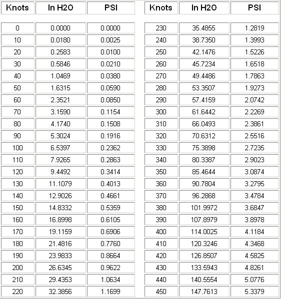
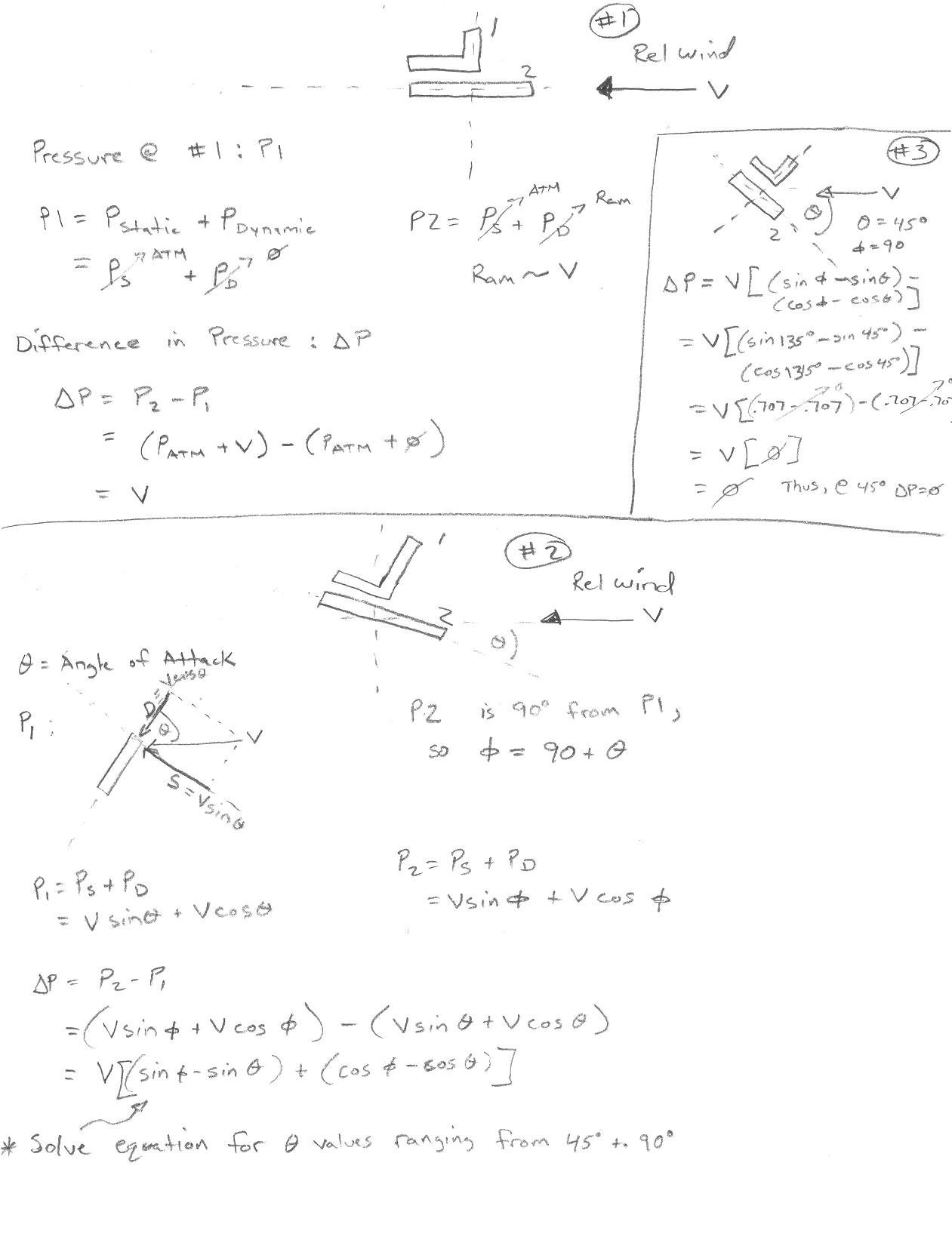
To understand differential pressure systems, you need to consider the geometry of the two probe orifices, which are best placed 90 degrees to each other. Because this is fixed, as the probe changes AoA, differing pressures will enter each orafice. Working through the geometry and math, the pressure in each orifice is the sum of the static and dynamic componenets entering it. For example, when the probe is oriented so that one orifice is directly into the prevailing wind, it sees a pressure equal to the ram (dynamic) pressure entering it. Conversly, since the other orifice is turned 90 degrees, all the airflow passes adjacent (normal) to the orafice and it sees only static pressure. This is the way a typical Pitot-Static setup works. However, as the angle between the orifice (I'll only refer to the first one, since the second is always going to be 90 degrees out of phase) and the prevailing wing changes, the orifice will no longer see the full ram pressure; part will enter, and part will pass normal to it. We can calculate the velocity component entering the orafice using trig functions (sin & cos of the angle), and we have graphs that relate air velocity to ram air pressure.
Working through the math, we can determine an equation that relates differential pressure (delta P) to Angle of Attack. However, it becomes clear that the relationship is still proportional to the relative wind velocity. In other words, the faster we are going, the more differential pressure will be created with Angle of Attack. This is where the differences between the LRI and a true AoA meter become apparent. The LRI makes no attempt to correct for this.
So why does the LRI work?
The LRI is initially calibrated at a specific airspeed and AoA (a full stall landing where the airplane just begins to mush). Reading the instructions, calibration is conducted by adjusting the angle of the probe (with respect to the wind cord line) until the needle of the LRI gage is right at the white line. Since the gage is nothing more than a sensitive pressure gage, essentially, you calibrate the probe to deliver a pre-set differential pressure (whatever the pressure is that lines up with the white line) at a pre-set flight condition (full mushing landing flare). The jump of logic here is that this full-mush flight condition corresponds to just under the critical angle of attack.
So what happens if you change the flight condition? Changing airspeed changes the maximum possible differential pressure. Essentially, to get the same differential pressure as you previously calibrated, but at a lower airspeed, you'll need a higher angle of attack. Similarly, go faster, and you'll need less angle of attack. Now take another look at the face of the LRI gage. Notice that the gage reads from red to green? This fixes the paradox of changing possible differential pressure.
Looking at our previous example, go slower than the calibrated flight condition but at the same AoA, the probe registers less differential pressure, and the gage reads red. Fly the same airspeed as the calibrated flight condition but at a lower angle of attack, the probe registers less differential pressure, and the gage reads red. Likewise, fly faster than the calibrated flight condition at the same AoA, the gage reads green. Eventually, at a great enough airspeed, any combination of airspeed and AoA you're likely to achieve will produce enough differential pressure to keep the gage in the green. This is the concept they refer to as "Lift reserve". Is it a valid concept? Generally, I think so. The range of critical angles of attack and stalling airspeeds is fairly narrow for most light aircraft. That means the range of differential pressures is also narrow, and moving the probe a few degrees one way or another can accommodate this range. Install the LRI is a very slow airplane or a jet, and all bets are off. The differential pressure at the stalling flight condition just won't work on that standard pressure gage.
Having gone through all that, I think the LRI concept does a fine job for what it's designed for, namely, answering the question "How close to stalling am I?" More than the desire to know the exact AoA at any given time, that's what we are most concerned with.
OK, Enough theory. What are we going to build?
To start with, I'm going to build an electronic version of the LRI. Why? Because it's easier to build, and does provide some valuable information to the pilot. I've drafted a design on a true angle of attack meter, and the electronics that make it work, but the integrated circuit I planned to use has been discontinued, and the only ones I can find that do what I want at more expensive than I want to pay right now ($60), so the LRI it is!
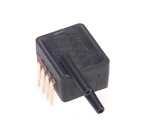
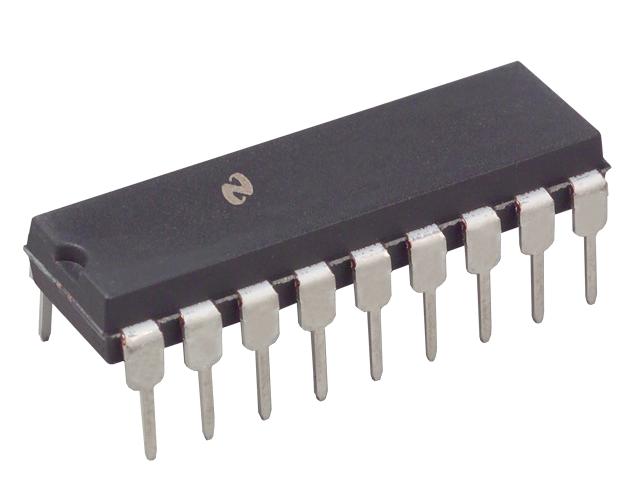
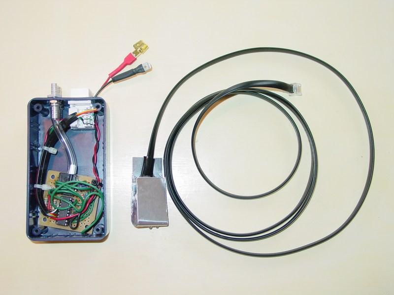
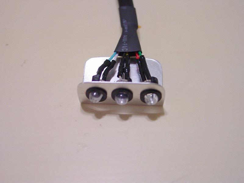
The concept for my AoA Meter is really quite simple. Construct a probe with two orifices 90 degrees apart. Plumb the tubing from the probe to a differential pressure sensor (a transducer with a range of 0-1 psi, or 0-10 inches of water) that will translate pressure to voltage. Run the voltage from the sensor into an IC that will turn on LEDs at pre-determined intervals. The IC I chose has 10 steps, so I could use a 10-digit LED bar graph, or a bank of LEDs. For my use, I'm simply going to use Red, Yellow, and Green LEDs: Red meaning "Warning, here comes the stall", Yellow for "Getting close to stalling AoA", and Green for "Good to Go".
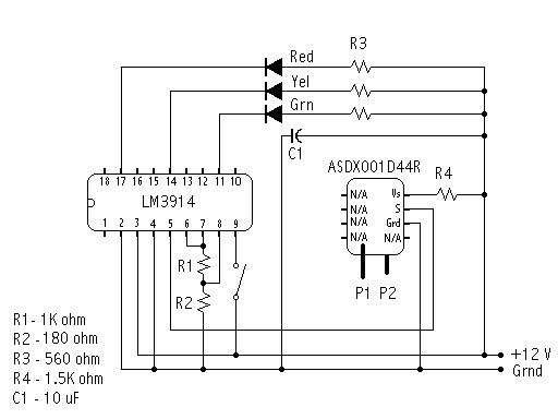
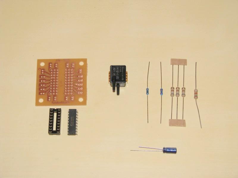
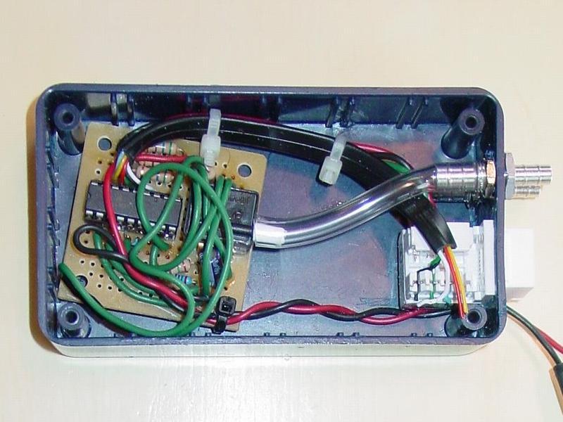
The Schematic is fairly straightforward, and all the parts are available from either Radio Shack or Digi-Key. The Bill Of Materials from Digi-Key came out to approximately $35. Throw in a few pieces from Radio Shack like the project enclosure and circuit board, and the bulkhead fittings from the local RC Hobby Shop, and the total comes to around $45. I've included the technical literature for the IC and pressure sensor.
I won't go into all the circuit design, but the resistor values were chosen for the specific components I used. Namely, if you change LEDs (which is perfectly OK), you may want to change the R3 resistor values to adjust the brightness to your liking. The values of R1 and R2 calibrate the pressure sensor output. If I were to build another AoA Meter, I might use a slightly different sensor (ASDXL10D44D) with a lower pressure range, Digi-Key PN 480-2528-5-ND, and change R2 to 1k ohm. This would give the meter a bit more sensitivity, although the current sensor seems to work fine.
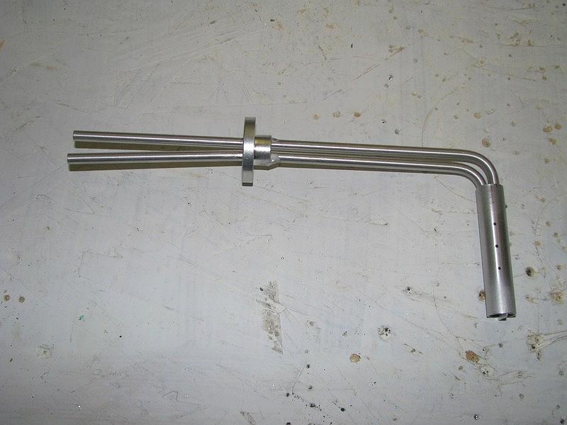
The probe is constructed from 5/8" dia tubing, and combines with a cut-down pilot static tube from Aircraft Spruce. This will then be mounted to the wing in a similar fashion to a standard pitot tube.
NOTE: photos link to full size image
|